Overview and Background
This challenge is initiated by the Id_Iot Project (IDentification for the
Internet Of Things), CHIST-ERA.
The IoT will contain a huge number of devices and objects that have very low or nonexistent
processing and communication resources, coupled to a small number of high-power
devices. The weakest devices, which are most ubiquitous, will not be able to authenticate
themselves using cryptographic methods. Other important tasks in the IoT will be to verify
if an object is authentic, or to identify an object. A promising way to address these issues is
to use Physical Unclonable Functions (PUFs). PUFs, and especially Quantum Readout PUFs,
are ideally suited to the IoT setting because they allow for the authentication and
identification of physical objects without requiring any crypto or storage of secret
information.
Furthermore, we foresee that back-end systems will not be able to provide security and
privacy via cryptographic primitives due to the sheer number of IoT devices. These
problems have to be addressed using privacy-preserving database structures and PUF
identification/authentication algorithms with good scaling behaviour.
This approach requires a solid understanding of PUF behaviour, i.e. the mechanism that transforms an optical PUF challenge into a response speckle pattern. Theoretical physics gives us a description of coherent strong scattering that is able to predict some global properties of speckle correlations, but not in sufficient detail to make unambiguous statements about the security/privacy/efficiency aspects of speckle-based identification and authentication. The purpose of the BOOST challenge is to leverage state of the art machine learning techniques to determine the boundaries of speckle-based security applications.
Optical PUF basics
"Speckle" is an interference phenomenon that occurs when coherent light (laser light) gets scattered by a rough surface or passes through a scattering substance. When viewed with a camera, the image consists of random-looking dark and bright blobs. This is called a speckle pattern. The pattern has a very strong dependence on the microscopic composition of the scattering substance. Furthermore, the speckle pattern is also very sensitive to the characteristics of the incoming light, e.g. angle of incidence, focus etc. As it is difficult to make a precise clone of strong-scattering objects, such objects are known as Physical Unclonable Functions (PUFs). An optical PUF essentially behaves like a keyed hash function, where the properties of the incoming light constitute the input, the configuration of the scatterers in the PUF is the key, and the exiting light is the hash value. The combination of an input and a PUF output is known as a Challenge-Response Pair (CRP). Optical PUFs can be used in various identification and authentication protocols. This is rather straightforward when the verifier has full control over the PUF. However, a number of protocols for remote authentication face the threat of spoofing attacks, especially lightweight protocols that rely on the secrecy of CRPs. Here it becomes important to known exactly how many independent CRPs a PUF can support, i.e. how many CRPs from a PUF the attacker must observe before he can start predicting responses. Another issue is privacy. In protols that involve a CRP-database- owning third party, it may be necessary to ensure that this third party does not learn which PUF is being authenticated/identified. For all these reasons it is important to have a good understanding of speckle statistics.Speckle statistics
The multiple scattering process in a PUF can be described using a model that is also used for fiber optics.
The incoming and exiting light are both described as a complex N-component vector.
Here N is the number of "modes" or transversal directions.
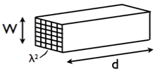
Let λ be the laser wavelength and let A be the illuminated area of the PUF;
then the number of modes is approximately N = π A/λ2.
In the picture below we have A=W2.
The average angular size of a speckle is λ/W.
Each complex entry in the vector says how much light is travelling in the corresponding direction, and wat the phase is. The "physical function" which maps the state of the incoming light to the response speckle pattern can be modelled as a complex N x N transmission matrix.
Camera pixels are sensitive to light intensity but not phase. The image recorded by a camera contains information only about the absolute value of the output-vector entries. Thus, even though the PUF physics is entirely linear, the recorded responses are a quadratic function of the challenge parameters and the transmission matrix elements. The entries of the transmission matrix are not mutually independent. A quick way of understanding this is by counting degrees of freedom. On the one hand, the transmission matrix has N2 complex degrees of freedom. On the other hand the PUF contains V/λ3 "voxels", volume elements that contain a small fixed amount of information that can be probed using light of wavelength labda. (Here "V" stands for the PUF volume through which light is diffusing. Typically V=Ad, where d is the thickness.) In practical PUF geometries the number of voxels is smaller than N2.
The implications are twofold.
(i) A PUF's transmission matrix contains less information than you would guess from its size. The information from the voxels is contained multiple times in the transmission matrix.
(ii) A speckle pattern leaks less information about the transmission matrix than you would guess from its size.
For details about speckle correlations we refer to the literature below.
- Statistical properties of laser speckle patterns. J. W. Goodman, in Laser Speckle and Related Phenomena, 2nd ed., J. C. Dainty, Ed. New York: Springer-Verlag, 1984.
- Correlations and Fluctuations of Coherent Wave Transmission through Disordered Media. S. Feng, C. Kane, P.A. Lee and A.D. Stone, Phys.Rev.Lett. Vol.61 No.7 (1988), pp 834--837.
For security applications of optical PUFs we refer to
- Physical One-Way Functions. R. Pappu et al., Science Vol. 297, Sept 2002, p.2026.
- Information-Theoretic Security Analysis of Physical Uncloneable Functions. P. Tuyls, B. Skoric, S. Stallinga, A.H.M Akkermans and W. Ophey. 9th Conf. on Financial Cryptography and Data Security 2005. LNCS 3570, pp 141-155
- Optical PUFs reloaded. U Rührmair, C. Hilgers, S. Urban, A. Weiershäuser, E. Dinter, B. Forster, C. Jirauschek. Cryptology ePrint Archive, Report 2013/215, 2013.
Modelling the experimental setup
As mentioned above, the events inside the PUF are typically modelled by a scattering matrix M, which specifies how light scatters from one mode to another. The light entering the PUF is represented as a complex-valued N-dimensional electric field vector E. The notation Ek stands for the complex "amplitude" of the electric field traveling in direction k. Note that k is a two-dimensional index standing for (kx,ky); there are N possible values of k that can exist inside the PUF. The light intensity in mode k is |Ek|2. The argument arg(Ek) is the phase of the light in mode k. The light that comes out of the PUF is similarly described as a complex vector F. The relation between E and F is given by
F = ME.This should be read as the matrix multiplication Fp = Σk MpkEk, where p=(px,py) is a two-dimensional index, and Σk is a summation over kx and ky. The matrix M has complex entries.
Modelling the PUF combined with the Spatial Light Modulator ('SLM', see setup) and the camera requires some extra work. First, the optics cannot capture all the N outcoming speckles, but a subset of size N'. Second, the camera is positioned such that each of the captured speckles covers multiple camera pixels. Hence one has to take into account a (dimensionality) mismatch between the output as predicted by the physical model and what is actually caught on camera. Note that the camera registers only the field strength ∝ |Fp|2, and the phase information is lost.
The optics at the input side
translates the phase setting on one SLM 'superpixel' (degree of fredom)
into the phase of one incoming direction.
Note however that the SLM is tuned to have not N degrees of freedom but only N'.
Hence there is a small mismatch between the incidence angles as
fed into the PUF by the challenge mechanism and the modes in the physical
model of the PUF.
A combined matrix model that maps the SLM confguration to a PUF output
will therefore work with a matrix T that is not square but N × N',
F = TS.Here S is a vector containing the pure phases as specified in the SLM configuration. (The term 'pure phase' means a complex number on the unit circle.) Note that the lenses in the setup have the effect of performing a two-dimensional Fourier transform: a location on the SLM is transformed by a lens into a direction (angle) of a plane wave incident on the PUF. Similarly, light exiting from the PUF in a certain mode is a plane wave moving in a certain direction; a lens maps this to a location on the camera's pixel array.